How Airplanes Fly — The Physics Behind Every Flight
Understanding the forces and principles that keep an aircraft in the air makes you a better, safer pilot — not just a more capable test-taker. When you understand why the stall happens, you recognize it earlier. When you understand load factor, you fly steep turns more precisely. This module builds the aerodynamics foundation everything else rests on.
- Describe the four forces of flight and their relationships in different flight regimes
- Explain how a wing generates lift using both Bernoulli's principle and Newton's third law
- Define angle of attack and explain its relationship to lift, drag, and the stall
- Calculate load factor for a given bank angle and explain its effect on stall speed
- Identify the three axes of rotation and the primary control surface for each
- Distinguish between positive and negative stability and explain their implications for flight
- Name the four left-turning tendencies and explain which is most significant at which phase
Lesson 1 — The Four Forces of Flight
Four forces act on an aircraft in flight simultaneously. The relationship between them determines whether the aircraft climbs, descends, accelerates, decelerates, or maintains steady flight. Every maneuver you perform is a deliberate adjustment of one or more of these forces.
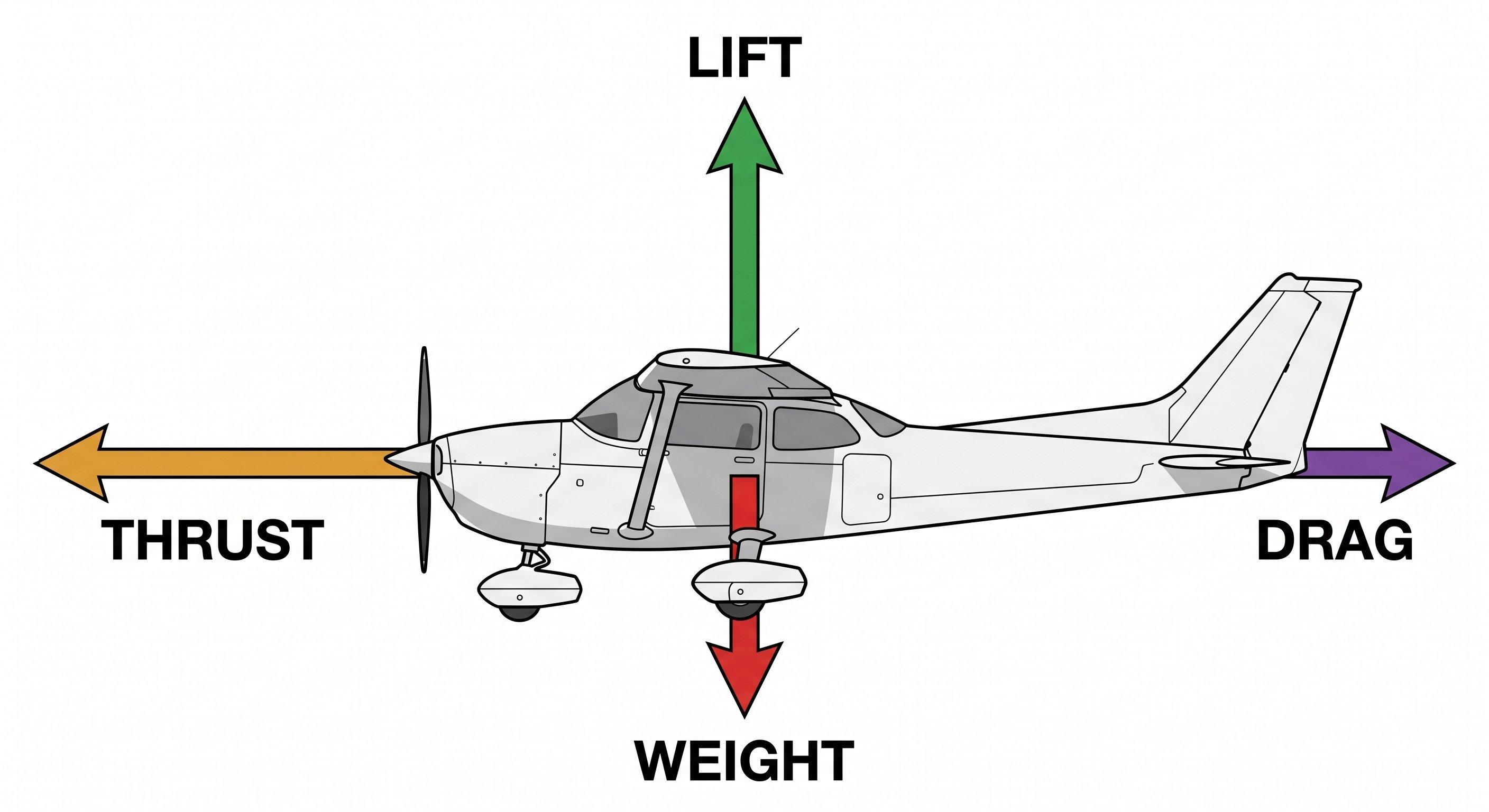
Lift is the aerodynamic force generated by the wings acting perpendicular to the relative wind — it is what holds the aircraft up. Lift is produced primarily by the wings and acts through the center of lift. In level flight, lift equals weight.
Weight is the gravitational force pulling the aircraft toward the center of the Earth. Weight acts through the center of gravity (CG). In level flight, weight equals lift. Weight is fixed (based on fuel load, passengers, and cargo) — the pilot cannot directly control it in flight, but it must be managed through loading decisions on the ground.
Thrust is the forward force produced by the propeller (and engine). Thrust acts roughly parallel to the aircraft's longitudinal axis. In level flight, thrust equals drag. The pilot controls thrust directly through the throttle.
Drag is the aerodynamic resistance to motion — it opposes the direction of flight. Drag is the price paid for any aerodynamic force production. There are two primary types: parasitic drag (form drag, skin friction, interference drag — increases with velocity) and induced drag (the byproduct of lift production — decreases with velocity). Total drag is at its minimum at a specific airspeed — the airspeed of maximum L/D ratio, which corresponds to best glide speed (Vg).
Force relationships in different flight regimes
Level flight: Lift = Weight, Thrust = Drag. No net acceleration in any direction.
Climbing: Thrust exceeds Drag (excess thrust accelerates upward). Lift is slightly less than Weight (because a component of thrust contributes to supporting weight in a climb). This surprises many students — in a climb, lift is not greater than weight; excess thrust is what produces the climb.
Descending: Drag exceeds Thrust, or Weight exceeds Lift. A power-off glide is sustained by weight (gravity) providing the forward component that replaces thrust.
Accelerating: Thrust exceeds Drag temporarily, producing acceleration.
Applying the four forces to every maneuver you fly
Most student pilots learn the four forces as a diagram and forget to apply them in the cockpit. Here's how they translate to actual stick-and-rudder work:
In a climb: You add power (more thrust) and pitch up. The increased thrust exceeds drag, and the increased pitch angle redirects some of that thrust component to support the aircraft against gravity. Counterintuitively, lift does NOT increase significantly in a normal climb — it's slightly less than weight, and excess thrust does the work. This is why the rate of climb depends primarily on excess power, not on how steeply you pull back.
In a descent: You reduce power. Thrust drops below drag. The aircraft slows and begins to descend. In a power-off glide, thrust is zero — gravity is now pulling the aircraft forward along a downward flight path, and that gravity component replaces the thrust that's gone. The aircraft is essentially "gliding downhill" using gravitational potential energy. Best glide speed minimizes the angle of that descent.
In level, slow flight: You've reduced power and raised the nose to maintain altitude. Drag has two components: induced drag is very high (high angle of attack) and parasite drag is low (slow speed). You're operating behind the power curve — the aircraft demands more power to fly slower because induced drag is so high. Adding more back pressure makes it worse, not better.
In a turn: The lift vector tilts with the bank. The vertical component of lift still must equal weight to maintain altitude — but now only part of lift is vertical. To get the same vertical lift component, total lift must increase — which means either increasing angle of attack (pulling back) or accepting a descent. This is why turns require back pressure to maintain altitude and why turns increase load factor.

Lesson 2 — How Lift Is Generated
Lift generation is one of aviation's most misunderstood topics — even by pilots who have been flying for years. Two principles work simultaneously to generate lift: Bernoulli's principle (pressure difference due to velocity difference) and Newton's third law (action-reaction from deflecting air downward).
Bernoulli's principle
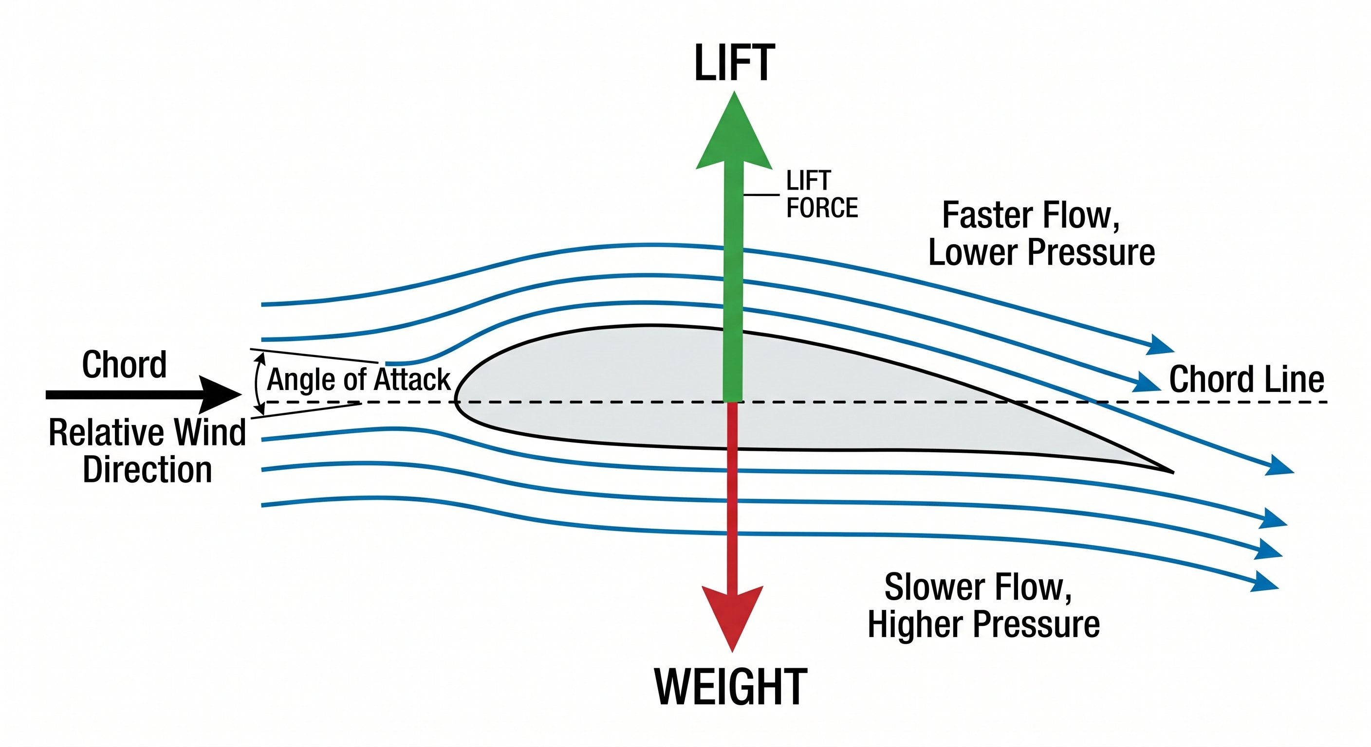
Bernoulli's principle states that in a flowing fluid, as velocity increases, pressure decreases. A wing's airfoil shape is designed so that air flowing over the upper (curved) surface accelerates and air flowing under the lower surface moves more slowly. The faster-moving air on top has lower pressure; the slower-moving air below has higher pressure. This pressure difference — higher below, lower above — produces a net upward force: lift.
The common misconception: textbooks often claim upper-surface air must "catch up" with lower-surface air at the trailing edge (the "equal transit time" theory). This is false — air over the top moves significantly faster and arrives at the trailing edge before the lower-surface air. The pressure difference is real, but the equal-transit explanation is not the correct reason for it.
Newton's third law — reaction lift
Simultaneously, the wing's angle of attack causes it to deflect air downward. By Newton's third law, if the wing pushes air down, the air pushes the wing (and aircraft) up. This reaction force is a significant component of lift, especially at higher angles of attack. At very high angles of attack (near the stall), reaction lift becomes increasingly dominant as the Bernoulli pressure differential breaks down.
Factors that affect lift production
Lift is governed by the lift equation: L = CL × ½ρV² × S, where CL is the coefficient of lift (determined by AOA and airfoil shape), ρ is air density, V is velocity, and S is wing area. In practical terms for pilots: lift increases with airspeed (V²), increases with air density (higher at sea level, lower at altitude), and increases with angle of attack (up to the critical AOA). Pilots control lift primarily by adjusting airspeed and angle of attack.
Why both theories are correct — and why it matters
Aviation instructors sometimes teach Bernoulli's principle or Newton's third law as the "real" explanation for lift, implying the other is wrong. Both are correct — they are two ways of describing the same physical phenomenon from different perspectives. What matters for flying is understanding the practical result: lift is proportional to angle of attack and airspeed, and it acts perpendicular to the relative wind.
The wing in practice — airfoil shape and its effect
The airfoil (cross-sectional shape of the wing) is designed to create a pressure differential at a useful range of angles of attack. A symmetric airfoil (same shape top and bottom) generates no lift at zero angle of attack but works well at high speeds — used in aerobatic aircraft. An asymmetric (cambered) airfoil like a Cessna 172's wing generates lift even at zero angle of attack and is more efficient at cruise speeds — ideal for trainers and light planes.
Chord line: The straight line from the leading edge to the trailing edge of a wing. This is the reference line for measuring angle of attack.
Camber: The curvature of the wing's mean line (halfway between top and bottom surfaces). More camber = more lift at low speeds, but more drag at cruise. High-lift aircraft have high camber; fast aircraft have thin, low-camber wings.
Relative wind: The direction of airflow relative to the aircraft — always opposite to the aircraft's direction of motion. If the aircraft moves forward and downward (as in a descent), the relative wind comes from forward and below. Angle of attack is always measured from the chord line to the relative wind.

Ground effect — why the airplane floats during landing
Ground effect is a real, practical phenomenon you'll notice on every landing. When a wing operates within approximately one wingspan of the ground, the ground interrupts the downwash of air behind the wing and reduces induced drag significantly — sometimes by 40–50%. The result: the aircraft generates more lift and less drag than it does at altitude for the same angle of attack and airspeed.
In practice, this means the aircraft will "float" in the flare during landing. You reduce power, flare to break the descent, and the airplane keeps flying longer than you'd expect. Don't add more back pressure to force it down — wait for the speed to bleed off and let it settle. Ground effect also affects takeoff: a heavily loaded aircraft may lift off and initially climb only within ground effect, then struggle to climb further. Never force an overloaded aircraft to climb by pulling back hard — let it accelerate in ground effect to a safe climb speed first.
Lesson 3 — Angle of Attack and the Stall
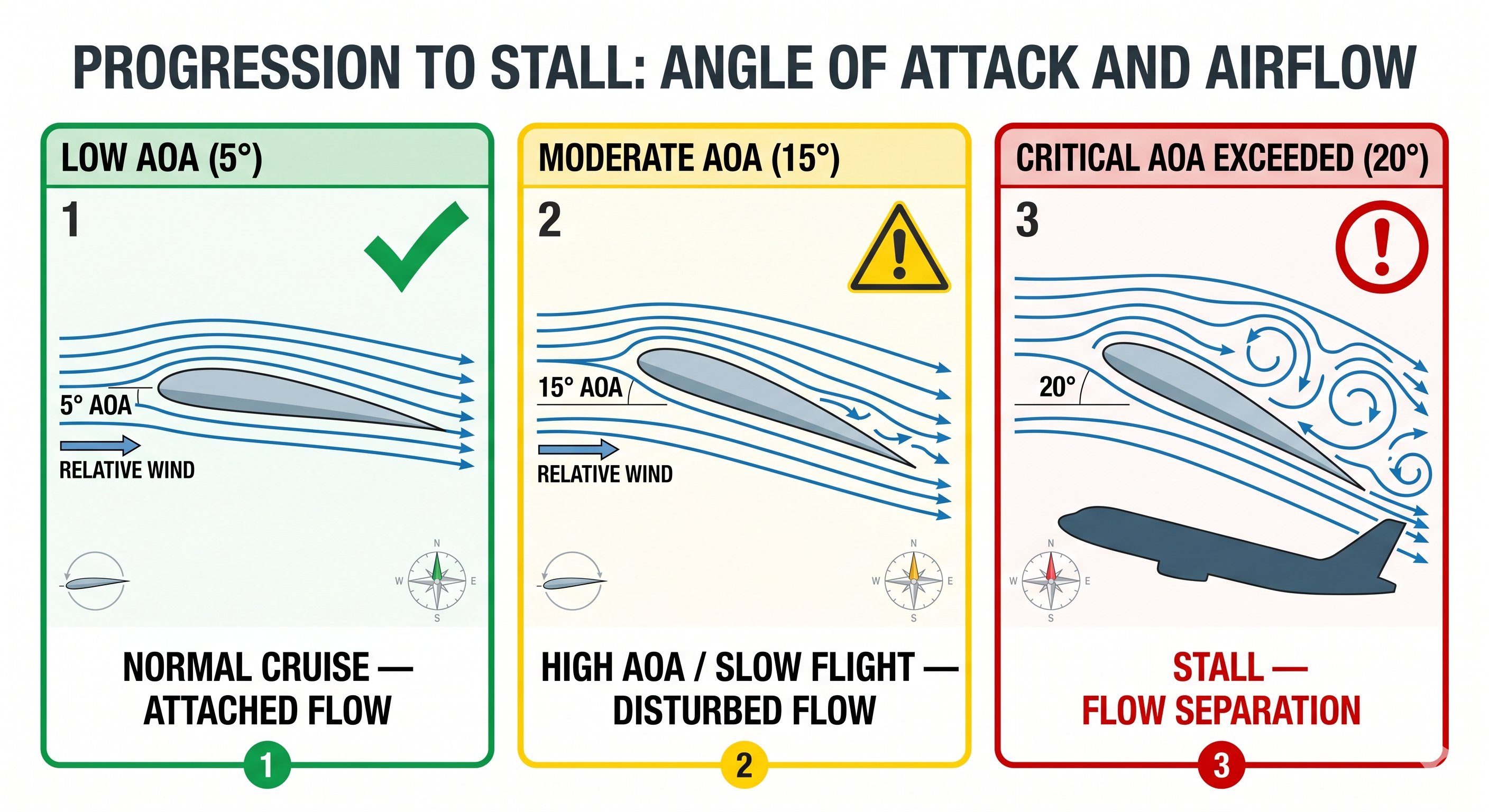
Angle of attack (AOA) is the angle between the wing's chord line (an imaginary line from leading edge to trailing edge) and the relative wind (the direction the air appears to come from, which is directly opposite the aircraft's flight path). AOA is the most important aerodynamic concept for safe flight — it determines whether the wing is generating adequate lift or approaching a stall.
The stall — a function of AOA, not airspeed
A stall occurs when angle of attack exceeds the critical angle of attack — approximately 18–20° for most light aircraft — causing the smooth airflow over the upper wing surface to separate and become turbulent. Lift drops dramatically. The stall is entirely determined by AOA, not by airspeed directly. This is the most important fact about stalls:
An aircraft can stall at any airspeed, in any attitude, at any power setting. Fast, slow, inverted, nose-down — if the angle of attack exceeds the critical AOA, the wing stalls. This is why stall recovery focuses on reducing AOA (nose forward) rather than adding power first. A high-speed stall in a steep turn at 120 kts is just as much a stall as a slow-flight stall at 45 kts.
Stall speed and load factor
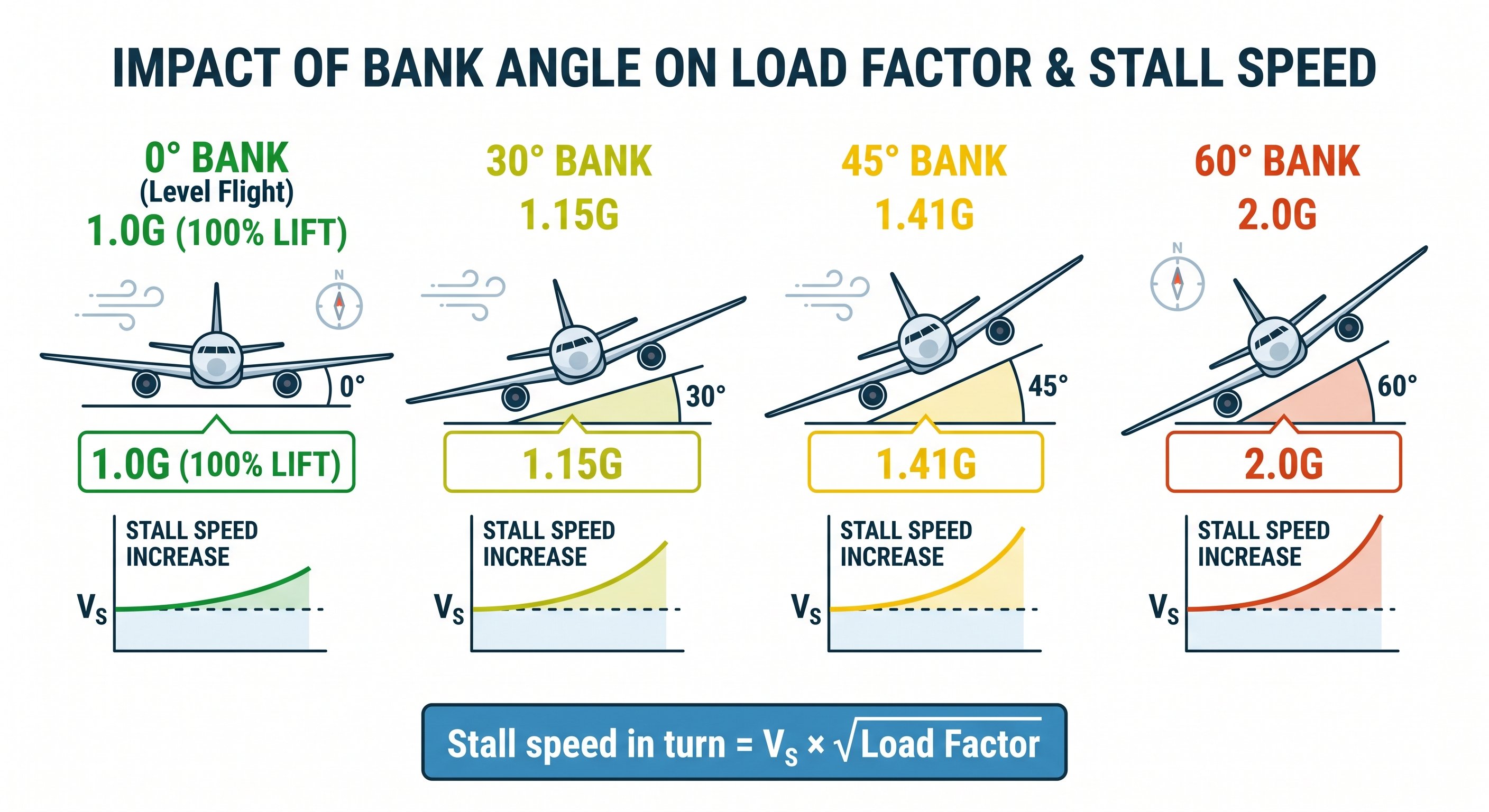
In straight-and-level flight at 1G, the stall occurs at the published stall speed (Vs). But stall speed is not constant — it increases with load factor. In any maneuver that increases load factor (banked turns, pullups from dives), the stall speed rises:
Stall speed in a maneuver = Vs × √(load factor)
At 45° bank (1.41G): stall speed = Vs × √1.41 = Vs × 1.19 (19% higher than published Vs)
At 60° bank (2.0G): stall speed = Vs × √2.0 = Vs × 1.41 (41% higher than published Vs)
Example: A Cessna 172 has a Vso (stall in landing configuration) of 40 kts. In a 60° bank turn:
Stall speed = 40 × 1.41 = 56.5 kts
A pilot flying at 65 kts in this bank is only 8.5 kts above stall — far less margin than in level flight. This is why steep turns near the ground are extremely dangerous and why entry into steep banks at low altitude kills pilots.
Stall recognition — what you actually feel before it happens
The stall warning system in most training aircraft (a reed in the leading edge that activates at 5–10 knots above stall) gives you several seconds of warning. But before the warning horn, there are aerodynamic cues that an alert pilot will notice:
- Mushy controls: The control surfaces lose effectiveness as the boundary layer begins to separate. The airplane feels heavy, sluggish, and unresponsive — inputs that would normally produce crisp responses feel like you're "pushing through mud."
- Buffet: The turbulent wake from the stalling wing strikes the tail, creating a distinctive shudder or vibration. This is particularly noticeable in the elevator and through the seat. Many pilots describe it as the airplane "shaking."
- High pitch attitude with low airspeed: If the airspeed is decreasing and the nose is high, the airplane is approaching a stall regardless of what the instruments say. Attitude + airspeed = situation awareness.

Stall recovery — the one thing that matters
Stall recovery has exactly one priority: reduce angle of attack. Everything else follows from that. The correct sequence:
- Push forward on the yoke/stick — reduce angle of attack below critical. This is counterintuitive because the nose is already low from the stall break, but you must positively reduce AoA, not just stop adding back pressure.
- Add full power — the increased thrust helps arrest the descent and provides energy to accelerate through stall speed.
- Level the wings — if in a banked turn when the stall occurs, level the wings with coordinated rudder and aileron to stop any roll/yaw tendency.
- Climb back to altitude — once flying speed is restored and descent is arrested, establish a climb to recover lost altitude.
The absolute most dangerous response to a stall is pulling back harder. This deepens the stall. It does not help. Muscle memory from early training — where pilots learn to pull back to stop a descent — is the instinct that kills people in stall-spin accidents. Training stalls repeatedly until recovery is automatic is the antidote.
Accelerated stalls and why they're dangerous
A stall can occur at any airspeed, any attitude, and any power setting — the only requirement is that angle of attack exceeds the critical value. An accelerated stall occurs when angle of attack reaches critical value at a higher-than-normal airspeed. This happens in pulling G-loads: a steep turn, a sharp pull from a dive, or a rough pull during turbulence. The stall is identical aerodynamically to a power-off stall but happens faster, more violently, and at a much higher airspeed. The recovery is the same: reduce AoA immediately.
Lesson 4 — Load Factor and Turns
Load factor is the ratio of the aerodynamic force (lift) acting on the aircraft to the aircraft's gross weight. In level, unaccelerated flight: load factor = 1.0 G. The wings support exactly the aircraft's weight. In any banked turn, the wings must provide both horizontal centripetal force and vertical lift — requiring them to generate more total force, increasing load factor.
| Bank Angle | Load Factor (G) | Stall speed increase | Structural limit |
|---|---|---|---|
| 0° | 1.0 G | None | Normal ops |
| 30° | 1.15 G | +8% | Normal ops |
| 45° | 1.41 G | +19% | Checkride standard |
| 60° | 2.0 G | +41% | Exceeds utility category limit |
| 75° | 3.86 G | +96% | Near structural limit of most GA aircraft |
| 90° | Infinite | — | Cannot sustain level flight |
Structural load limits
Light GA aircraft are certified in different categories with different load limit factors: Normal category (most trainers): +3.8G / −1.5G. Utility category: +4.4G / −1.8G. Aerobatic category: +6.0G / −3.0G. These are limit loads — the structure must sustain them without permanent deformation. The ultimate load is 1.5× the limit load — above which structural failure may occur. Maneuvering speed (Va) is the maximum speed at which full control deflection will not exceed the structural limit load.
Load factor in your everyday flying
Load factor sounds like an academic concept but you encounter it on every flight that includes a turn. In a 60-degree banked turn, the load factor is 2 Gs — every structure in the aircraft is experiencing twice its normal load, including the wing. The stall speed in that same 60-degree turn is 1.41 times the normal stall speed. If your Cessna 172 normally stalls at 48 knots clean, it stalls at approximately 68 knots in a 60-degree bank. That 20-knot difference is the margin between controlled flight and an accelerated stall.
| 30° bank | 1.15 G | Stall speed × 1.07 |
| 45° bank | 1.41 G | Stall speed × 1.19 |
| 60° bank | 2.00 G | Stall speed × 1.41 |
| 75° bank | 3.86 G | Stall speed × 1.97 |
Maneuvering speed (Va) — why you slow down in turbulence
Maneuvering speed (Va) is the maximum speed at which you can apply full deflection of a single control surface without risk of structural damage. Below Va, the wing will stall before it reaches the structural limit. Above Va, you can exceed the aircraft's structural load limits with a single abrupt input. When you hit significant turbulence, slow to or below Va. This is not because the turbulence itself is less at Va — it's because if the turbulence causes an abrupt large G-load, the wing stalls before it breaks. The stall is recoverable; structural failure is not.
Va is published in the POH and is listed on the placard in the cockpit. Important: Va decreases with decreasing aircraft weight. A lighter aircraft has a lower Va because the wing can reach structural limits at lower airspeeds. The Va on the placard is for maximum gross weight — if you're flying significantly lighter, your actual Va is lower.
The base-to-final stall-spin — the accident that kills most often
The stall-spin on the base-to-final turn is the most common fatal accident in light aircraft. Here's exactly how it unfolds: the pilot turns from base to final and overshoots the centerline. Worried about landing long or going around, they add back pressure and increase bank to tighten the turn. The increasing bank requires more back pressure to maintain altitude, which increases angle of attack. The uncoordinated skidding turn (inside rudder, too much bank) creates a higher load factor on the inside wing. The inside wing stalls first. The aircraft rolls toward the stall and the nose drops — but at 300–500 feet AGL, there is no altitude for recovery. This accident happens at slow speed, high angle of attack, in an uncoordinated skidding turn at low altitude. All of those conditions are present on every base-to-final turn that goes wrong. Recognition of the setup is the prevention.
Lesson 5 — Three Axes of Rotation and Control Surfaces
An aircraft rotates about three axes, each passing through the center of gravity. Pilots control rotation about each axis using the primary control surfaces.
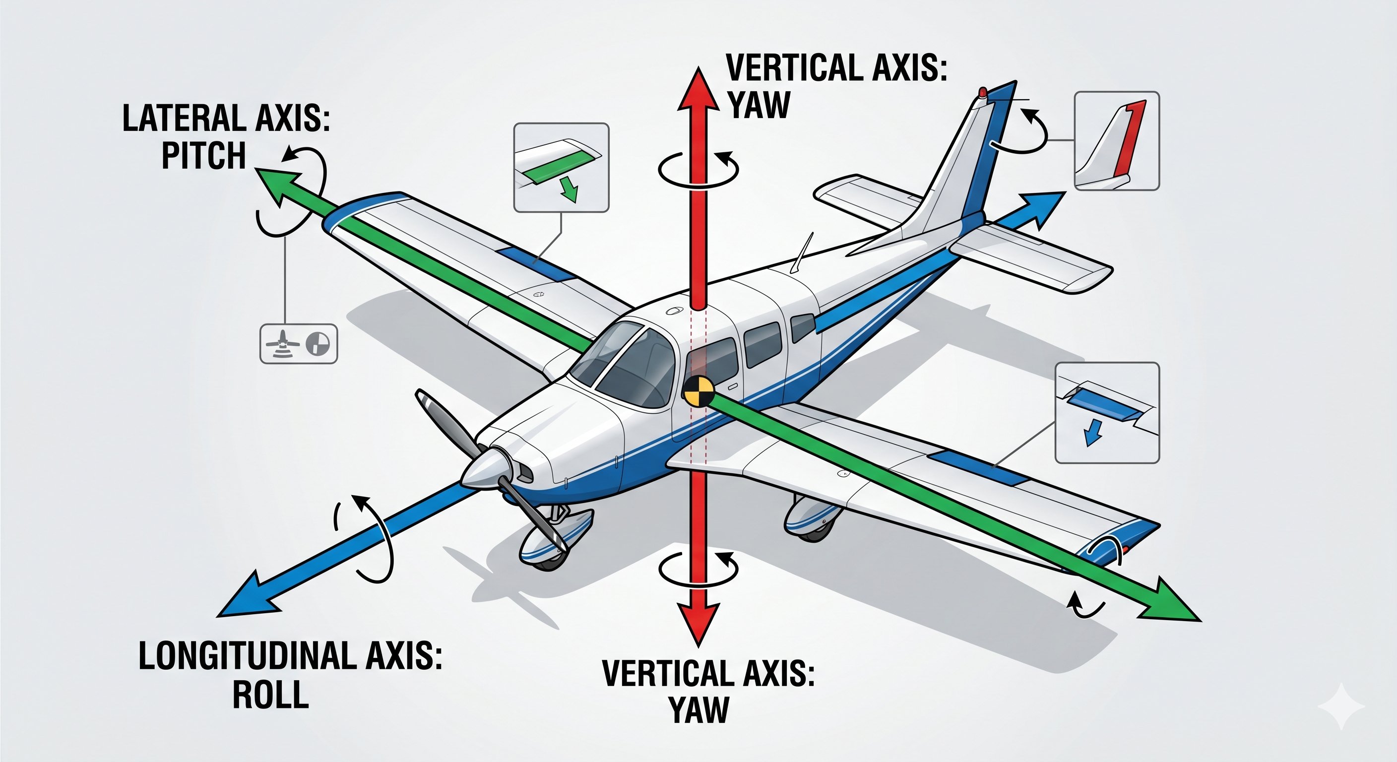
| Axis | Orientation | Movement | Primary control | Secondary controls |
|---|---|---|---|---|
| Lateral | Wingtip to wingtip | Pitch (nose up/down) | Elevator | Stabilator, elevator trim |
| Longitudinal | Nose to tail | Roll (bank left/right) | Ailerons | Spoilers, flaperons |
| Vertical | Top to bottom | Yaw (nose left/right) | Rudder | Differential thrust |
Adverse yaw — why the rudder matters
When you deflect the ailerons to initiate a roll, an unwanted yaw occurs in the opposite direction of the intended turn. This is adverse yaw — caused by the descending aileron (on the rising wing) generating more induced drag than the ascending aileron on the opposite wing. The down aileron increases the wing's angle of attack and generates more lift but also significantly more induced drag, which yaws the nose away from the turn.
The correction: coordinate rudder with aileron. Apply rudder in the direction of the turn when rolling in, neutralize when established in the bank, apply opposite rudder when rolling out. The ball in the slip/skid indicator tells you if you are coordinated — keep the ball centered. Uncoordinated flight increases stall risk, reduces aircraft performance, and is uncomfortable for passengers.
Flaps — secondary lift and drag control
Flaps are hinged surfaces on the trailing edge of the wing inboard section. When extended, they increase the wing's camber (curvature), generating more lift and more drag simultaneously. They lower the stall speed (by increasing Clmax at any given AOA) — allowing slower approach and landing speeds. They also increase drag, which steepens the approach glidepath. Different flap positions make different tradeoffs: small flap extension (10°) adds mostly lift with little drag — useful for short-field takeoff. Full flap (40°) adds maximum drag and lift — ideal for approach and landing.
How the control surfaces actually work in flight
Control surfaces work by changing the shape of the wing or tail surface, which changes the aerodynamic force that surface produces. Understanding the mechanism — not just the result — makes you a more precise pilot.
Ailerons: When you roll right, the right aileron moves up and the left aileron moves down. The down aileron increases the camber (curvature) of the left wing, generating more lift. The up aileron reduces camber on the right wing, generating less lift. The difference in lift between the two wings creates the rolling moment. The problem: the down aileron also creates more induced drag on the left (higher-lift) wing — this is adverse yaw. The aircraft tends to yaw left (opposite the roll) when rolling right. This is why coordinated rudder input accompanies aileron input: right rudder when rolling right corrects the adverse yaw tendency.
Elevator: The elevator controls pitch by changing the lift on the horizontal tail. Up elevator creates negative lift (downward force) on the horizontal stabilizer, which rotates the nose up. The important concept: the elevator controls angle of attack and therefore airspeed in a glide. In a power-off descent at best glide, raising the nose (up elevator) increases angle of attack — this initially seems to slow the descent, but the increased drag actually increases the descent rate. The elevator controls pitch attitude; the throttle controls altitude in normal flight.
Rudder: The rudder controls yaw — but it is not used to turn the aircraft. This surprises many new pilots. Turns are initiated with ailerons (bank → turn). The rudder's primary jobs are: (1) correcting adverse yaw, (2) maintaining coordinated flight, (3) crosswind correction on the ground and in slips, and (4) countering left-turning tendencies at high power. The ball in the inclinometer tells you if the rudder input is correct: ball centered = coordinated flight.

Trim — the underused tool in a student pilot's cockpit
Trim adjusts the neutral position of a control surface so the aircraft maintains a given attitude without continuous control pressure. Most training aircraft have elevator trim and some have rudder trim. Student pilots often hold pressure on the controls for extended periods instead of trimming — this causes fatigue, reduces precision, and diverts attention. The correct technique: establish the desired attitude and power, then trim until the control pressure is zero. From that point, you're flying with fingertips, not muscle.
In a Cessna 172, you'll use nose-up trim in slow flight and landings, and nose-down trim in cruise. During climbs, you'll trim to hold the climb airspeed without back pressure. During descent, you'll trim to hold the descent airspeed. Every power change should be followed by a trim adjustment — power changes change airspeed, which changes the required trim.
Lesson 6 — Aircraft Stability
Stability is the tendency of an aircraft to return to its original flight condition after a disturbance. Stability is built into the aircraft's design — not something the pilot provides. Understanding stability is essential for understanding why aircraft behave as they do, and why some configurations are more hazardous than others.
Positive static stability
Positive static stability means the aircraft tends to return toward the original condition immediately after a disturbance — like a ball at the bottom of a bowl. Push the nose down; the aircraft naturally wants to pitch back up. This is the designed behavior of nearly all training aircraft. Positive longitudinal stability is provided primarily by the horizontal tail — it acts as a weathervane, keeping the nose aligned with the relative wind.
Positive dynamic stability
Static stability describes the initial tendency after a disturbance. Dynamic stability describes the long-term behavior. Positive dynamic stability means the oscillations caused by a disturbance dampen out over time until the aircraft returns to original trim. Most GA aircraft have positive dynamic stability in all three axes — disturbances naturally dampen without pilot input.
Center of gravity and stability
CG position profoundly affects longitudinal stability. Forward CG increases longitudinal stability — the aircraft is more resistant to pitch disturbances and more stable, but requires more back pressure to maintain flight attitude, and the stall speed increases slightly. Aft CG decreases stability — the aircraft becomes more responsive (and possibly unstable) in pitch. Exceeding the aft CG limit can produce an aircraft that is unrecoverable from a stall. Weight and balance calculations before every flight are not bureaucratic exercise — they are genuine airworthiness requirements.
Stability in practice — what you actually feel in the airplane
Stability isn't abstract — you feel it every time you release the controls. A positively stable aircraft (like a Cessna 172) tends to return toward its trimmed attitude when disturbed. A neutrally stable aircraft stays wherever you put it. A negatively unstable aircraft diverges from any disturbed position. Training aircraft are designed to be positively stable to make learning easier and to give pilots time to respond to disturbances.
Longitudinal stability (pitch): Disturb the nose up. A stable aircraft will oscillate — nose rises, then falls, then rises again but less, until it settles back at the trim attitude. This phugoid oscillation has a long period (20–40 seconds in most light planes) and small amplitude. You can let a stable aircraft fly itself through minor turbulence. An unstable aircraft would diverge — the nose would continue rising or falling with no tendency to return.
Lateral stability (roll): Bank the wings and release the controls. Dihedral (the upward angle of the wings from root to tip) creates restoring lift on the lower wing when the aircraft slips, rolling the aircraft back toward level. A well-designed aircraft will roll back toward wings-level on its own after a small bank disturbance. But if the bank is significant, the aircraft will also yaw (the raised wing moves faster, generates more lift), entering a spiral descent — Dutch roll in some aircraft, spiral dive in others. This is why you don't just let a trainer fly itself in a steep bank.

CG position and its effect on stability and control
The center of gravity (CG) position has an enormous effect on how the aircraft handles. This is why weight and balance is not just a regulatory checkbox — it directly affects flight characteristics.
Forward CG: More stable, heavier elevator feel, higher stall speed (the horizontal tail must produce more downward force to balance), more elevator back pressure required in landing. Hard to flare — you may not be able to hold the nose up sufficiently in the landing flare if CG is too far forward. The forward CG limit exists because of this control limitation, not structural limits.
Aft CG: Less stable, lighter elevator feel, lower stall speed (less downward tail force needed). More responsive but more dangerous — reduced pitch stability means the aircraft doesn't recover as readily from pitch disturbances. An aft CG also makes stall recovery more difficult because the nose pitches up more readily and the aircraft is less inclined to recover. The aft CG limit is primarily a stability limit.
Before every flight, verify that CG falls within the approved envelope for the loaded weight. An out-of-CG aircraft may be uncontrollable.
Lesson 7 — Left-Turning Tendencies
Single-engine propeller aircraft have four aerodynamic forces that tend to turn the aircraft to the left (for aircraft with standard right-hand rotating propellers, viewed from the cockpit). Understanding these forces helps you apply the correct control inputs — particularly right rudder at high power and low airspeed — without confusion.
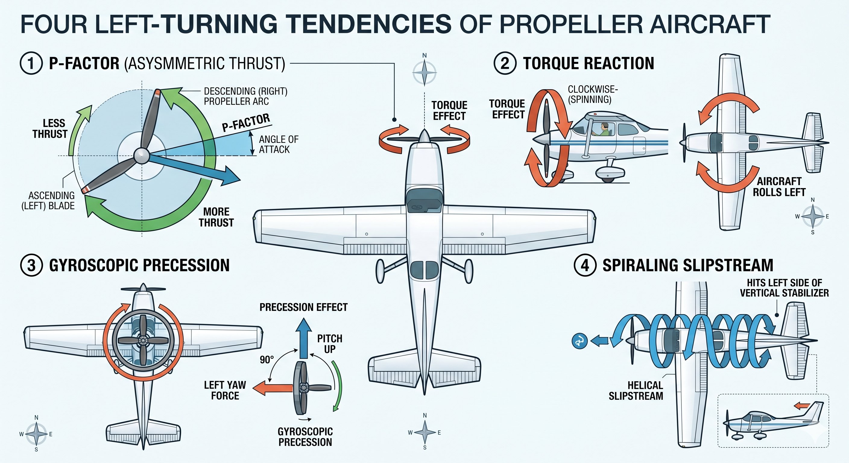
P-factor (Asymmetric blade effect)
At high angles of attack (takeoff, climb), the descending propeller blade on the right side of the aircraft has a greater angle of attack than the ascending blade on the left — generating more thrust on the right side. This asymmetric thrust creates a yawing moment to the left. P-factor is most significant at high power and high AOA — exactly the conditions of takeoff and initial climb.
Torque
Newton's third law applies to the propeller: as the engine rotates the prop clockwise (viewed from the cockpit), the engine and airframe experience an equal and opposite rolling tendency to the left. This torque rolling tendency is most noticeable at low airspeeds when aerodynamic control is less effective.
Gyroscopic precession
The spinning propeller acts as a gyroscope. When a force is applied to a gyroscope, the resulting precession occurs 90° later in the direction of rotation. During tailwheel aircraft takeoff, as the tail is raised (tilting the gyroscope forward), the precessing force is felt as a yawing tendency to the left. Gyroscopic precession is more significant in tailwheel aircraft and less in nosewheel (tricycle gear) aircraft.
Spiraling slipstream
The propeller's rotation imparts a spiraling rotation to the slipstream — the air flowing back from the propeller. This spiraling air strikes the left side of the vertical stabilizer, generating a yawing force to the left. Most significant at lower airspeeds where the slipstream is more concentrated relative to the airflow over the tail.
The practical takeaway: All four left-turning tendencies are most pronounced simultaneously at high power, low airspeed, and high angle of attack — which is exactly the condition during takeoff and initial climb. Apply right rudder to maintain centerline during the takeoff roll and initial climb. As airspeed increases and angle of attack decreases in cruise, left-turning tendency diminishes and right rudder requirement decreases. Your CFI will help you develop the feel for the right amount of right rudder in each phase.
- Four forces: Lift (up, perpendicular to relative wind) · Weight (down, CG) · Thrust (forward, engine/prop) · Drag (aft, opposing motion).
- Level flight: Lift = Weight, Thrust = Drag. Climb: excess Thrust over Drag — not Lift over Weight.
- Lift generation: Bernoulli (pressure differential from velocity difference) + Newton (reaction to downward deflection of air). Both operate simultaneously.
- Angle of attack: angle between chord line and relative wind. The ONLY cause of stall — not airspeed, not attitude.
- Stall occurs when AOA exceeds critical AOA (~18–20°). Can stall at any airspeed, any attitude, any power setting.
- Load factor: 45° bank = 1.41G, 60° bank = 2.0G. Stall speed = Vs × √(load factor). At 60°: stall speed rises 41%.
- Three axes: Lateral (pitch, elevator) · Longitudinal (roll, ailerons) · Vertical (yaw, rudder).
- Adverse yaw: nose yaws away from turn when rolling. Correct with rudder in direction of turn.
- Four left-turning tendencies: P-factor · Torque · Gyroscopic precession · Spiraling slipstream. All peak at high power + low airspeed + high AOA (takeoff and initial climb).
- Aft CG reduces longitudinal stability — can make stall recovery impossible if beyond aft CG limit. Always compute weight and balance.
When each tendency is most prominent — and how to correct
The four left-turning tendencies don't all show up with equal strength at all times. Understanding when each is most significant helps you apply the right corrective input at the right moment.
P-factor: Most pronounced at high angle of attack with high power. This means it's most significant during the initial climb after takeoff and in slow flight. The right blade of the propeller sweeps through a larger arc of air than the left blade, producing more thrust on the right side, yawing the nose left. Correction: right rudder, applied continuously as long as the condition persists.
Torque reaction: Most pronounced at high power settings with the aircraft at rest or slow. As the engine turns the propeller clockwise (viewed from the cockpit), Newton's third law creates a reaction that rolls the airframe counterclockwise (left). In flight, this manifests as a tendency to roll left. On the takeoff roll in a tailwheel aircraft, it creates a pronounced left turn tendency. Correction: right rudder (which also corrects the yaw produced by the rolling tendency through asymmetric main gear forces).
Slipstream effect: The propeller accelerates air rearward and imparts a spiral rotation to it. This rotating slipstream corkscrews around the fuselage and strikes the left side of the vertical stabilizer, producing a yawing force to the left. This effect is constant whenever the propeller is turning but is most significant at high power and slow speed. Correction: right rudder.
Gyroscopic precession: The propeller acts as a gyroscope. When a force is applied to a spinning gyroscope, the reaction appears 90 degrees ahead in the direction of rotation. This becomes significant when the pitch attitude changes rapidly — most notably in tailwheel aircraft when the tail is lifted on the takeoff roll. As the tail rises, the top of the propeller disc is pushed rearward; the gyroscopic reaction yaws the nose to the left. Correction: right rudder, applied as the tail rises.
The practical result — how much right rudder?
On takeoff roll in a Cessna 172, you'll apply right rudder almost from the start of the roll. As speed builds and the aerodynamic effectiveness of the rudder increases, you'll gradually reduce the pressure — the rudder needs less deflection at higher airspeeds. On initial climb, right rudder keeps the ball centered. In cruise, the combined left-turning tendencies are small enough that slight right rudder or a rudder trim adjustment handles them. In a power-off glide, the left-turning tendencies largely disappear (low power = reduced P-factor, slipstream, and torque) — you'll find yourself reducing right rudder.
The ball in the turn coordinator is your real-time indicator of coordination. Ball centered = coordinated. Ball to the right = not enough right rudder (or too much left). Ball to the left = too much right rudder (or too much right). Step on the ball: if the ball rolls left, add left rudder; if it rolls right, add right rudder.
Lesson 8 — Drag, Glide Performance, and Propeller Aerodynamics
Drag in depth — the two types
Parasite drag increases as airspeed increases — it's the aerodynamic friction and pressure drag of the aircraft moving through the air. Form drag (from the shape of the aircraft), skin friction drag, and interference drag (where surfaces meet) are all parasite drag. Double the airspeed and parasite drag quadruples.
Induced drag is the byproduct of lift production. As an airfoil generates lift, it creates wingtip vortices — spiraling air that trails behind each wingtip. These vortices represent energy lost from the system. Induced drag is highest at high angles of attack (slow flight) and decreases as airspeed increases.
Total drag is the sum of both types. At low airspeeds, induced drag dominates. At high airspeeds, parasite drag dominates. Total drag is minimum at the airspeed where the two curves intersect — this is the best L/D ratio airspeed, which equals best glide speed (Vg) in most light aircraft.
Glide performance
Glide ratio describes how far an aircraft travels horizontally for every foot it descends. A Cessna 172 has approximately a 9:1 glide ratio — for every 9,000 feet of altitude, it can glide roughly 9 nautical miles (accounting for no-wind conditions). The key facts about glide performance:
- Best glide speed (Vg) is fixed in calm air — flying faster or slower than Vg reduces glide distance
- Wind affects glide distance, not glide ratio — into a headwind, fly faster than Vg to maximize distance over the ground; with a tailwind, fly slower
- Weight does not affect glide ratio — a heavier aircraft glides at the same ratio but at a higher airspeed. The glide ratio (distance per altitude lost) stays the same; the descent rate increases proportionally
- Propeller drag — a windmilling (spinning) propeller creates significant drag. If the engine fails, a feathered prop (on aircraft with that capability) dramatically improves glide ratio; a stopped prop is slightly better than a windmilling one
Propeller aerodynamics
The propeller is a rotating wing — each blade is an airfoil that generates thrust the same way a wing generates lift. The propeller converts engine torque (rotational force) into thrust (forward force). Key propeller concepts for the written test and oral exam:
Propeller pitch — the angle of the propeller blade relative to the plane of rotation. A fixed-pitch propeller has one pitch angle; a constant-speed (variable-pitch) propeller adjusts pitch automatically to maintain a set RPM regardless of airspeed and power. Most training aircraft have fixed-pitch props.
Slipstream effect — the propeller accelerates air rearward and imparts a rotational component (clockwise when viewed from the cockpit for most US aircraft). This rotating slipstream strikes the vertical stabilizer at an angle, producing a left-turning tendency — the aircraft tends to yaw left. Right rudder counteracts this.
P-factor (asymmetric thrust) — at high angles of attack, the descending propeller blade (right side, viewed from cockpit) moves through a greater slice of air than the ascending blade. The right blade produces more thrust, creating a left-yawing moment. P-factor is most pronounced at high power and high angle of attack — takeoff and climb.
Torque reaction — Newton's third law: as the engine turns the propeller clockwise, the airframe reacts by tending to rotate counterclockwise (roll left). This is one of the left-turning tendencies most noticeable at high power settings.
Gyroscopic precession — the propeller acts as a gyroscope. When a force is applied to a spinning gyroscope, the reaction occurs 90 degrees later in the direction of rotation. This affects the aircraft when the nose is rapidly pitched up or down — most noticeable in tailwheel aircraft during the takeoff roll as the tail is lifted.
Best glide vs. minimum sink — why they're different and when to use each
There are two important glide speeds that serve different purposes:
Best glide speed (Vg / Vbg): The airspeed that gives the greatest horizontal distance per foot of altitude lost. Use this after an engine failure if you're trying to reach a specific landing area — a field, a road, an airport. Vg is published in the POH and is typically shown on a white arrow on the airspeed indicator.
Minimum sink speed: The airspeed that gives the lowest rate of descent in feet per minute. This is slower than best glide. Use minimum sink if you're already over your landing area and need to extend time aloft — waiting for emergency equipment, burning off altitude before landing, or waiting for a better moment to commit to the landing spot. You'll lose more horizontal distance at minimum sink, but you'll stay up longer.
In a real engine-out emergency: fly best glide to your chosen landing area, then transition to whatever approach technique maximizes your landing success. Losing altitude rapidly once over the field is not a problem — high, wide overhead pattern entries give you more options than a desperate straight-in from miles away.

The propeller as a drag device
A windmilling propeller — one that's spinning because airflow is turning it rather than because the engine is driving it — creates significant drag. In most light aircraft with fixed-pitch props, you cannot stop the propeller after engine failure; it will windmill. This drag measurably reduces glide ratio. Aircraft with constant-speed propellers can feather the blades (align them with the airflow) after engine failure, dramatically reducing drag and improving glide ratio. This is one reason high-performance and twin-engine aircraft have constant-speed props.
A practical note: immediately after an engine failure, while running through the engine restart checklist, maintain best glide speed. Don't spend the first critical seconds looking for the field while the airspeed diverges from best glide. Fly the airplane first, troubleshoot second, navigate third.