Navigation — Finding Your Way Across the Sky
Navigation is the skill of knowing where you are, knowing where you want to go, and reliably getting there. This module builds your navigation toolkit from the ground up — chart reading, course conversion, dead reckoning, VOR use, E6B calculations, and cross-country flight planning. Every concept is taught with worked examples you can practice before your written test and checkride.
- Convert true course to magnetic heading using the TVMDC sequence with worked examples
- Read sectional charts including airport symbols, airspace boundaries, MEFs, and VOR compass roses
- Apply pilotage and dead reckoning techniques in combination for cross-country navigation
- Use a VOR receiver to determine position and track to or from a station
- Solve time-speed-distance, fuel, and wind correction problems on the E6B
- Explain GPS limitations for VFR operations and what RAIM means
- Plan a complete VFR cross-country flight from chart to departure
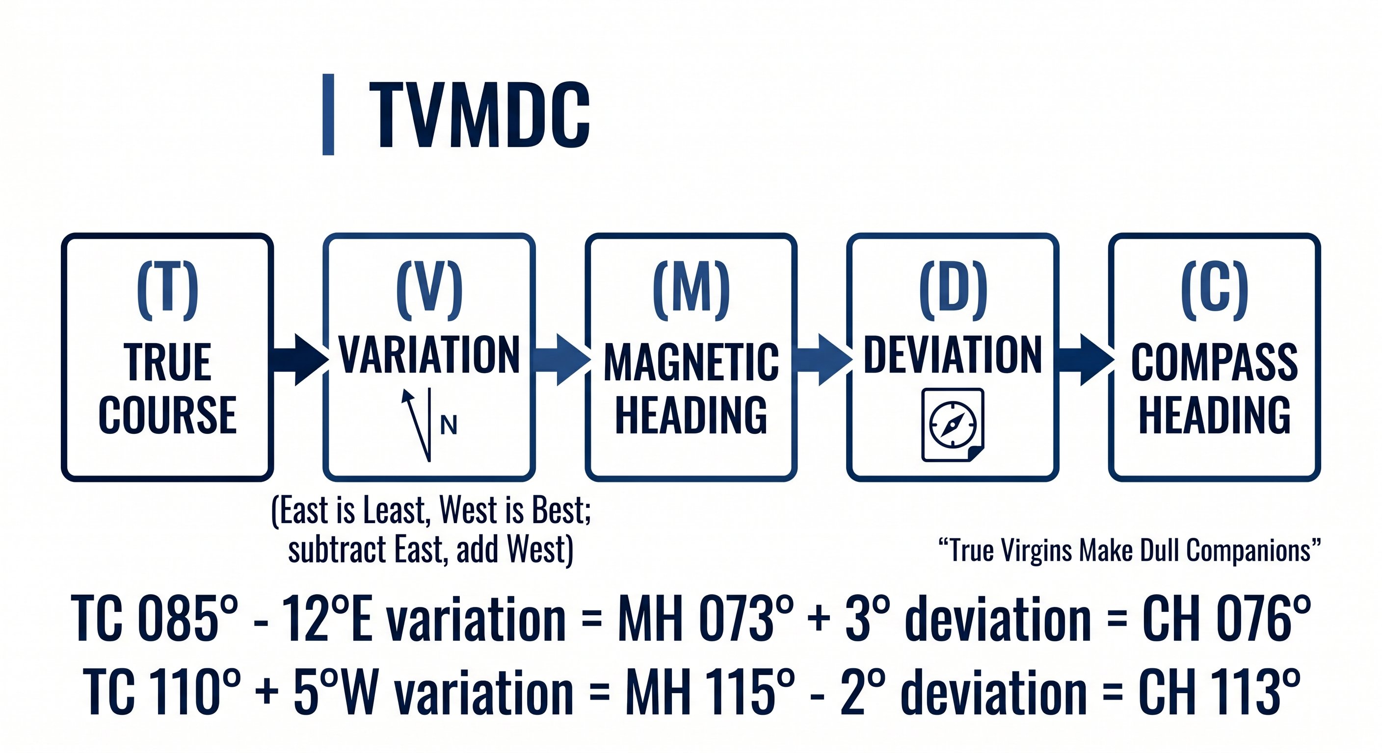
Lesson 1 — True Course to Compass Heading: The TVMDC Conversion
Every cross-country flight starts with a line drawn on a chart. That line gives you a true course — measured from geographic north. But your aircraft's heading indicator and compass work from magnetic north, and your compass itself has additional errors. Before you can fly the course, you must convert it through a series of corrections.
The conversion sequence is TVMDC — a mnemonic remembered as "True Virgins Make Dull Companions." Working left to right converts chart course to what you dial into the cockpit. Working right to left reverses it.
Step 1 — True Course (TC)
True course is the direction of your intended path measured clockwise from true (geographic) north. You measure it from a sectional chart using a plotter aligned to the nearest meridian (line of longitude). Meridians run true north-south, so aligning your plotter to one gives a true measurement. True course doesn't change with location — it's a fixed geometric angle between your departure and destination.
Step 2 — Magnetic Variation (V): "East is Least, West is Best"
Magnetic variation is the angular difference between true north and magnetic north at a specific location. Magnetic north is currently located in northern Canada — not at the geographic North Pole — so compass needles across the US point in slightly different directions from true north depending on where you are.
Variation is depicted on sectional charts as isogonic lines — dashed magenta lines connecting points of equal variation, labeled with their value and direction (e.g., "12°W"). The agonic line (zero variation) runs roughly through the eastern Mississippi Valley. East of it: easterly variation. West of it: westerly variation.
The rule: East is Least, West is Best. Subtract easterly variation, add westerly variation when converting TC to MC.
Worked example — applying variation:
True course: 270° (due west). Variation: 15°E (eastern US).
MC = TC − East variation = 270 − 15 = 255°
True course: 090° (due east). Variation: 10°W (western US).
MC = TC + West variation = 090 + 10 = 100°
Step 3 — Magnetic Course (MC)
Magnetic course is what your compass would read if it had no local errors. It accounts for the difference between true and magnetic north but not for the aircraft's own magnetic interference. In some parts of the US, variation is substantial — in Seattle it's about 16°E; in Maine it's about 16°W. Flying coast to coast requires applying very different variations.
Step 4 — Deviation (D): The Compass Correction Card
Every aircraft has its own magnetic personality. The engine, wiring, avionics, and metal structure create a local magnetic field that deflects the compass needle slightly from magnetic north. This error — called deviation — is different for every aircraft and varies with heading. A Cessna 172 on a heading of 360° might have 2° of easterly deviation, while on a heading of 180° it might have 3° of westerly deviation.
The deviation correction card is mounted on or near the compass in the cockpit. It lists the compass correction needed for various magnetic headings, usually in 30° increments. You read the card for the heading nearest your magnetic course and apply the correction.
Step 5 — Compass Heading (C)
Compass heading is what you set on your heading indicator (DI) and what you physically fly. It's the magnetic course corrected for deviation — the number that, when you hold it precisely, actually tracks you along your intended route.
Complete worked example — TVMDC:
Planning a flight from your home airport. You measure a true course of 055° on the chart. Your sectional shows isogonic lines indicating 8°W variation in your area. Your compass correction card shows +2° deviation at 060°.
TC = 055°
V = 8°W → West is Best → Add: 055 + 8 = 063° MC
D = +2° → Add: 063 + 2 = 065° compass heading
You set 065° on your heading indicator and fly that heading. Your actual ground track (given no wind) will be 055° true — your intended course.
Common exam trap: The question may give you a magnetic course and ask for compass heading, or give TC and ask for MC only. Read the question carefully — TVMDC has multiple steps and the question may be asking for an intermediate result, not the final compass heading.
Lesson 2 — Reading the Sectional Chart
The VFR sectional aeronautical chart is your primary navigation document. Published at a scale of 1:500,000 (one inch equals approximately 6.86 nautical miles), each chart covers about 340 × 340 miles and is updated every 56 days. Using an outdated chart for navigation is a FAR violation — always verify your charts are current before flight. See our sectional chart reading guide →
Airport symbols — the most important marks
Every airport on the chart has a symbol whose color and fill pattern tell you critical information before you even look at the data block.
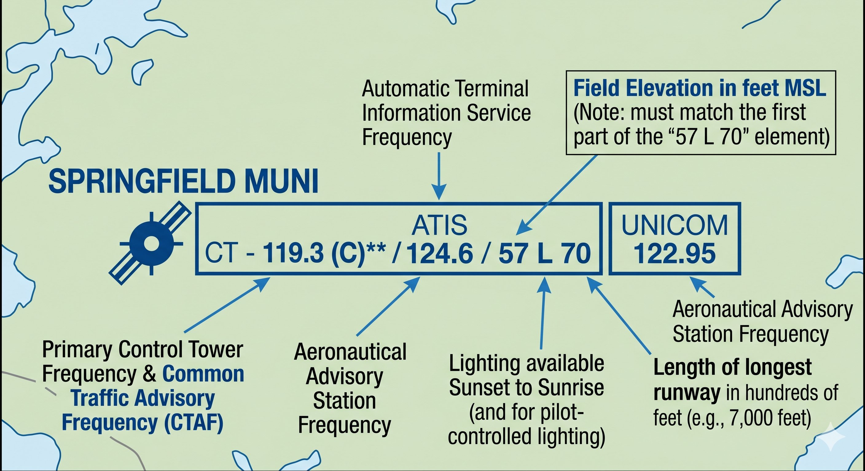
The airport data block — decoded
Every charted airport has a data block adjacent to its symbol. Reading top to bottom, you'll find: airport name, elevation in feet MSL, control tower frequency (if towered, prefixed "CT-"), ATIS/ASOS frequency (if available, prefixed "A" or "A*" for ASOS), longest runway length in hundreds of feet (70 = 7,000 ft), and UNICOM frequency. A star (*) next to the elevation indicates pilot-controlled lighting. An "L" indicates the airport has runway lighting.
Maximum Elevation Figures (MEF)
Scan your sectional and you'll see large blue numbers — typically 4 to 5 digits — sitting in the middle of each latitude/longitude quadrant. These are Maximum Elevation Figures (MEF). They represent the height of the highest known terrain or obstacle in that quadrant, rounded up to the next 100 feet and then increased by an additional 100 feet of buffer. Flying at or above the MEF provides clearance from all charted obstacles in that quadrant.
MEF example: A quadrant shows MEF "42" — this means 4,200 ft MSL. The highest known terrain or obstruction in that quadrant is no higher than 4,100 ft MSL (the 100 ft buffer was added). Flying at 4,500 ft gives you 400 ft of clearance above all charted objects in that quadrant. In mountainous terrain, MEF values may be 12,000 ft or higher — always check before flying unfamiliar terrain.
Isogonic lines and measuring true course
The dashed magenta lines you see crossing the chart diagonally are isogonic lines — connecting points of equal magnetic variation. When measuring true course with your plotter, align the plotter to the nearest meridian. The angle between the meridian and your course line is the true course. Then apply the variation shown by the nearest isogonic line to convert TC to MC.
Distance measurement: one degree of latitude equals exactly 60 nautical miles. The latitude scale printed on the left and right margins of the sectional chart can be used directly as a nautical mile scale — simply transfer with your plotter. One minute of latitude = one nautical mile.
VOR compass roses
VOR stations on the chart appear as hexagons surrounded by a compass rose. The compass rose shows magnetic bearings from the VOR station — it is already corrected for local variation. When you see a VOR compass rose, you can visually estimate which radial you would be on from any position on the chart. This quick situational awareness check is valuable during cross-country navigation.
Airport symbols — the most information-dense icon on the chart
Each airport on a sectional chart is a small circle with additional details packed around it. Learning to decode airport symbols quickly is one of the highest-return chart-reading skills:
- Magenta circle: Non-towered airport (no control tower, or tower not in operation)
- Blue circle: Towered airport (control tower in operation)
- Tick marks around the circle: Airport has services (fuel, maintenance) — hard-surface runways
- No tick marks: Airport may have limited services or turf/dirt runways
- Numbers next to the airport: Field elevation (e.g., "4229" = 4,229 ft MSL) and longest runway length in hundreds of feet (e.g., "90" = 9,000 ft)
- CT frequency shown: Tower frequency listed if the airport has a tower
- Star symbol: Airport has a rotating beacon (lit at night)
- R in a circle: REIL (Runway End Identifier Lights) installed

Obstacles and terrain — the life-critical information
The sectional chart shows man-made obstacles (towers, antennas, buildings) with specific symbols. The symbol and associated numbers tell you everything you need to know:
Tower symbol (lightning bolt): A guy-wired tower. The bold number next to it is the MSL altitude of the top. The smaller number in parentheses is the AGL height. For example, "2,450 (350)" means the top is 2,450 ft MSL and 350 ft tall. Always use the MSL figure to determine whether you clear it at your planned altitude.
Group obstruction symbol: Multiple towers in the same area — shown as a cluster. The highest obstacle's MSL altitude is given.
Terrain shading: The background color of the chart represents terrain elevation — from green (low) through yellow and brown to gray-purple at very high elevations. This gives you an immediate visual sense of terrain relief along your route. Always verify planned altitudes against both charted obstacles AND terrain contours, especially in mountainous areas.
Maximum Elevation Figure (MEF): The large blue numbers in each quadrangle (the grid squares on the chart) represent the highest obstacle or terrain in that quadrant plus a safety buffer. Flying above the MEF provides at least 300 feet of clearance above all charted objects in that quadrangle. MEF is a good reference for minimum safe altitude in unfamiliar areas.
VOR symbols, airways, and navaids
VOR stations appear as compass rose symbols on the sectional — a circle with a hexagonal outline (or a simple compass rose). The station name, frequency, and identifier are printed nearby. Victor airways (V-xxx) connect VOR stations and are shown as light blue lines with the airway designation labeled. Airways provide a navigation framework for cross-country flying and are used by both VFR and IFR pilots, though VFR pilots are not required to fly airways.
NDB (Non-Directional Beacon) stations are shown as magenta circles with an anchor symbol. NDBs are gradually being decommissioned and are less critical for modern navigation, but some are still in use and appear on sectionals.
Lesson 3 — Pilotage and Dead Reckoning
Before GPS, before VORs, pilots navigated using two fundamental techniques: pilotage (looking out the window and matching the ground to the chart) and dead reckoning (calculating where you must be based on where you started, how fast you went, and for how long). Today, both remain essential skills — required on your checkride, and more reliable than electronics when technology fails.
Pilotage — navigating by visual landmarks
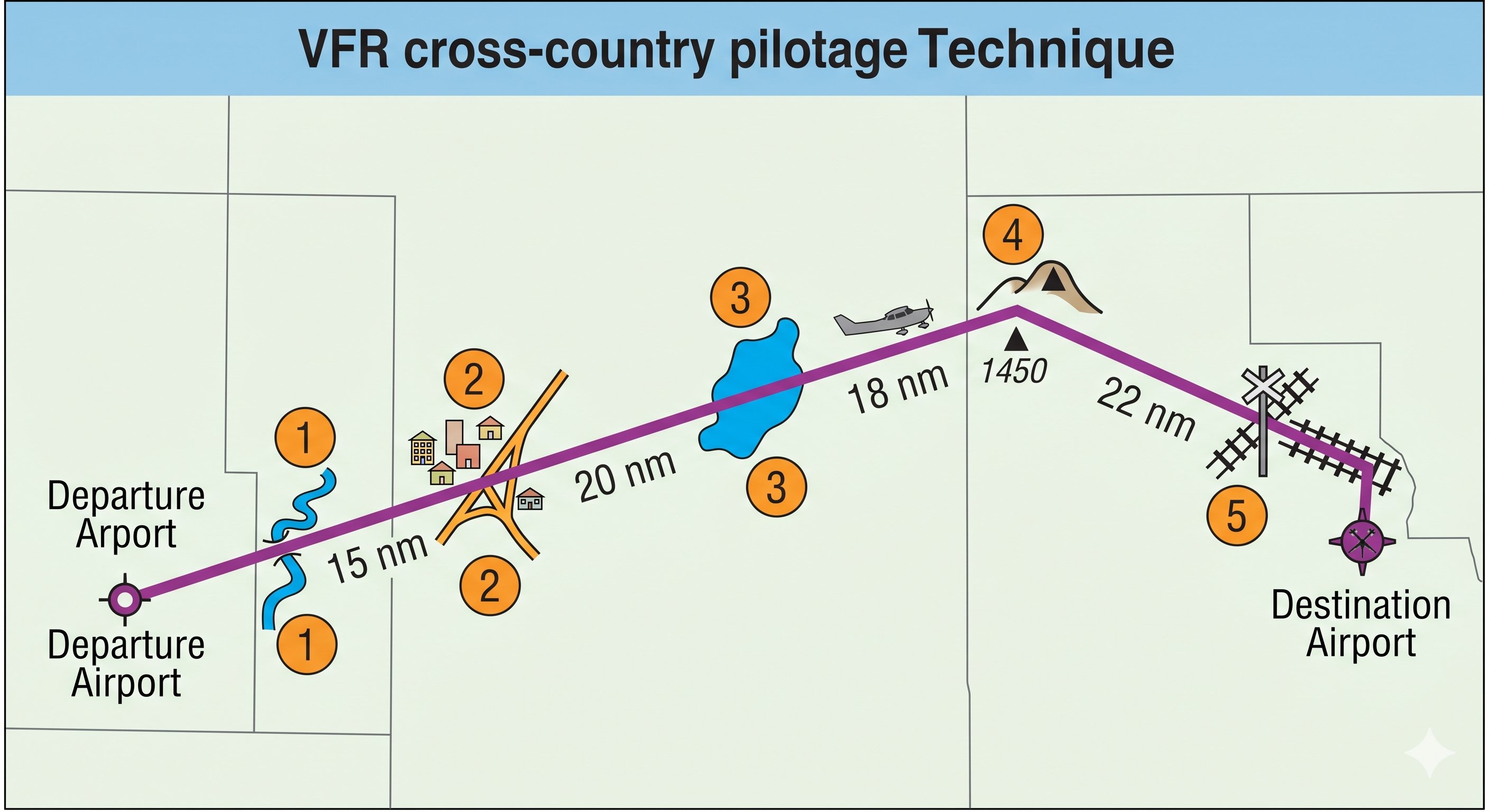
Pilotage is navigation by visual reference to ground features identified on the chart. The technique requires discipline and a methodical approach. Effective pilotage pilots:
- Pre-select checkpoints before the flight — choose features that are unmistakable from the air. A large lake is better than a pond. A freeway interchange is better than a country road. A prominent hill is better than a gentle rise. Space checkpoints 15–25 nm apart so you're checking position every 10–15 minutes at cruise speed.
- Identify two features simultaneously at each checkpoint. Single-feature identification is risky — similar features exist throughout the country. A river and a highway crossing it, confirmed together, is much more reliable than either alone.
- Look ahead, not just down. As you approach a checkpoint, orient yourself to what the chart shows should be visible ahead of you. Matching a panoramic view to the chart is faster than searching for a single feature directly below.
- Don't rationalize.} If the ground doesn't match the chart at your checkpoint, you are not where you think you are. Stop rationalizing features into matching and identify your actual position before continuing.
When you can't find your position: Fly to a large, unmistakable landmark — a significant river, a major city, a large lake, or a VOR — and positively fix your position from there before replanning. Pressing on while genuinely uncertain of your position is one of aviation's most preventable mistakes. Lost and landed safely beats lost and continued until fuel exhaustion.
Dead reckoning — calculating position mathematically
Dead reckoning (DR) calculates current position from a known starting point by applying your heading, true airspeed, time elapsed, and wind correction. It is the basis of the navigation log (nav log) you complete before every cross-country.
The core DR relationship: Distance = Groundspeed × Time. Rearranged: Time = Distance ÷ Groundspeed, or Groundspeed = Distance ÷ Time. If you know any two, you can solve for the third.
Dead reckoning worked example:
Departing checkpoint Alpha at 10:00 Zulu. Groundspeed 115 kts. Distance to checkpoint Bravo: 46 nm.
Time to Bravo = 46 ÷ 115 = 0.40 hours = 0.40 × 60 = 24 minutes
Estimated arrival at Bravo: 10:24 Zulu
When you arrive at Bravo at 10:27 Zulu (3 minutes late), your actual groundspeed was: 46 ÷ (27/60) = 46 ÷ 0.45 = 102 kts — about 13 kts slower than planned. You have more headwind than forecast. Recalculate your ETAs and fuel accordingly.
Combining pilotage and DR produces more reliable navigation than either technique alone. Fly dead reckoning between checkpoints, then use pilotage to confirm your position at each checkpoint. If your dead reckoning ETA and your pilotage position agree — you're on track. If they diverge, investigate before continuing.
Pilotage in practice — training your eye to match ground to chart
Pilotage is navigation by visual reference to landmarks on the ground — rivers, roads, towns, lakes, railroads, and terrain features — compared against the sectional chart. It sounds simple but requires deliberate practice. The challenge: the ground from 4,500 feet looks nothing like a map. Distances compress. Colors flatten. Small towns look similar. The skill is pattern recognition — looking for distinctive combinations of features that together uniquely identify your position.
Effective pilotage technique: choose large, unambiguous checkpoints visible from miles away — a distinctive lake shape, a major highway interchange, a city with a recognizable water tower. Don't choose features that might look like many others (a small pond, a two-lane road). Mark your checkpoints on the chart before flight and estimate when you should see each one based on groundspeed. If you arrive at the estimated time and see the checkpoint — you're on track. If you don't see it — stop, orbit, and positively identify your position before continuing.

Dead reckoning — the math that keeps you on course
Dead reckoning is position estimation based on a known starting point, a measured heading, an airspeed, and elapsed time. It answers the question: "If I started here, flew this heading at this speed for this long — where am I now?" Dead reckoning accuracy degrades over time because errors in heading and airspeed compound. It's most accurate over short legs (15–30 minutes) and degrades on longer legs, especially in crosswind conditions.
The key formula: Distance = Groundspeed × Time. If your groundspeed is 110 knots and you've been flying for 25 minutes, you've covered 110 × (25/60) = 45.8 nautical miles. Compare this to your planned position — if your chart shows the checkpoint should be 45 nm from your last fix and it appears in front of you, dead reckoning has worked.
Wind correction is the critical variable. A 15-knot crosswind at 105 knots TAS creates a track error of approximately 8 degrees if not corrected. After 30 minutes, that's a position error of approximately 4 nautical miles — enough to miss a small airport entirely. Use the E6B to calculate the wind correction angle (WCA) before flight, and apply it to your magnetic heading throughout the leg.
The 1-in-60 rule — estimating track error in flight
When you suspect you've drifted off course, the 1-in-60 rule gives you a quick correction. The rule: 1 degree of track error results in 1 nautical mile of displacement per 60 nautical miles flown. If you've flown 30 nm and estimate you're 2 nm off course, your track error is approximately 4 degrees (2 nm ÷ 30 nm × 60 = 4°). Apply a correction of 4 degrees toward the course line — plus an additional 4 degrees to intercept rather than just parallel the course — for an intercept angle of 8 degrees total. Once back on course, reduce by the original error correction and fly the planned heading.
When lost: don't panic. Maintain controlled flight first. Identify your last known position and the time since you were there. Draw a circle of uncertainty around that position based on your speed and elapsed time. Look for a large distinctive landmark in that circle. Climb if terrain allows — more altitude means more landmarks visible and better radio/GPS reception. Call Flight Service (122.2 MHz on VORs, or 121.5 MHz) if you can't positively identify position within a few minutes. Tell them your situation — this is not an emergency, it's a navigation problem.
Lesson 4 — VOR Navigation
VOR (VHF Omnidirectional Range) is a ground-based navigation aid that broadcasts on VHF frequencies between 108.0 and 117.95 MHz. VOR stations transmit 360 magnetic radials — bearings measured FROM the station — which properly equipped aircraft receivers detect and display. VORs remain valuable navigation aids even in the GPS era, and VOR interpretation is tested on every Private Pilot written exam.
How the VOR system works
Each VOR transmits two signals simultaneously: a reference phase signal broadcast in all directions, and a rotating directional signal. The phase difference between the two signals at the aircraft's location corresponds directly to the magnetic bearing from the VOR to the aircraft. Your VOR receiver processes this phase difference and displays it on the CDI (Course Deviation Indicator).
VOR identification is broadcast as a Morse code signal (and sometimes voice) on the VOR frequency. You must positively identify a VOR before navigating by it — this means listening for and recognizing its 3-letter Morse code identifier. Never navigate on a VOR you haven't identified. If the station is under maintenance, the identifier will be absent or replaced with the letters "T-E-S-T" — do not navigate on it.
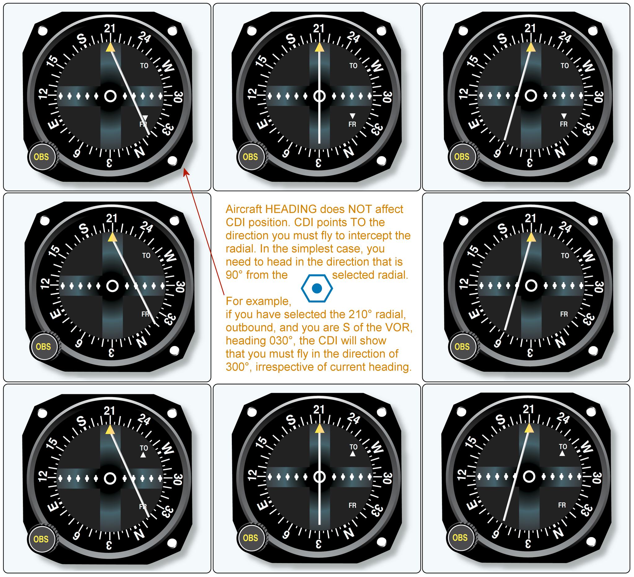
Using the VOR CDI — step by step
The VOR instrument has three moving parts: the OBS (Omni-Bearing Selector, the knob you turn), the CDI needle (the vertical line that deflects left or right), and the TO/FROM flag (showing whether the selected course takes you toward or away from the station).
To determine your position from a VOR: Tune and identify the VOR. Slowly rotate the OBS until the CDI centers with a FROM flag — the number in the OBS window is your radial (your bearing FROM the station). If the CDI centers with a TO flag, you are on the reciprocal — add or subtract 180°.
To navigate TO a VOR: Tune and identify. Rotate the OBS until you get a TO flag with the CDI roughly centered, setting your desired inbound course. Fly to keep the CDI centered. When the needle deflects, turn toward the needle — fly toward where the needle is pointing, not away from it. Each dot of deflection typically represents 2° of course error.
The reversed sensing trap: If you have a FROM flag selected when flying toward the station, or a TO flag when flying away, the CDI needle deflects in the opposite of the correct correction direction. Always match your flag (TO when flying toward, FROM when flying away). Flying with reversed sensing and correcting the wrong way is a common written test trap and a real in-flight hazard.
VOR limitations
VOR accuracy is ±1° under ideal conditions, but degrades with distance and terrain. VORs have published service volumes — the ranges within which reception is guaranteed at specific altitudes. Terminal VORs (T) serve within 25 nm, Low Altitude VORs (L) within 40 nm below 18,000 ft, and High Altitude VORs (H) within 100 nm at higher altitudes. Using a VOR beyond its service volume is unreliable and not recommended for navigation.
How the VOR CDI actually works — the most misunderstood instrument
The Course Deviation Indicator (CDI) shows whether you are to the left or right of the selected VOR radial — but it does not point toward the station. This confuses almost every student at first. The needle shows your relationship to the selected course, not the direction of the station.
To use a VOR correctly: tune and identify the station (listen for the Morse code identifier). Then turn the OBS (Omni Bearing Selector) until the needle centers with a TO indication. The OBS now shows the magnetic bearing to the station. Fly that magnetic heading (corrected for wind) and the CDI will stay centered as long as you track that radial.

Reverse sensing — the trap that causes pilots to fly in circles
Reverse sensing occurs when you're flying away from the station on a course that has a FROM indication, but you try to track the needle as if you were flying toward the station. The result: the needle deflects left, you turn left to correct, the needle deflects further left, you turn more left — you end up spiraling away from the course. The needle deflects opposite to what you expect because the geometry reverses when you're flying away from the station.
Prevention: always verify the TO/FROM flag before correcting toward the needle. If the flag shows FROM and you're flying toward the station's radial, expect the instrument to work normally. If FROM and you're flying outbound on the radial — the needle still shows deviation correctly, but you must interpret it correctly: needle right with FROM means turn right to return to course (same as with TO). The needle always deflects toward the course line, regardless of TO or FROM. The confusion comes from which direction to turn — always turn toward the needle.
Identifying your position with two VORs
A VOR radial tells you you're on a specific line from that station — but not how far along that line. To get a precise fix, you need two VORs. Tune the first VOR, center the needle with a FROM indication, and note the radial. Then tune the second VOR, center the needle, and note that radial. Your position is where those two radials intersect. This is a VOR cross-fix — a position accurate to within a mile or two depending on distance from the stations.
In practice with modern GPS, two-VOR cross-fixes are less critical than they once were. But understanding the technique helps you understand radials, and cross-checking your GPS position against a VOR radial is a useful habit when flying in areas with good VOR coverage.
VOR service volumes and reception limits
VORs have defined service volumes — the range within which the station provides reliable signals. High-altitude VORs (designated H) provide reliable coverage from 1,000 ft AGL to 45,000 ft within 130 nm. Low-altitude VORs (L) cover 1,000–18,000 ft within 40 nm. Terminal VORs (T) cover 1,000–12,000 ft within 25 nm. Below these distances, you cannot rely on VOR signal accuracy for navigation. Always check the sectional for the VOR designation and ensure you're within the service volume before using it as your primary navigation reference.
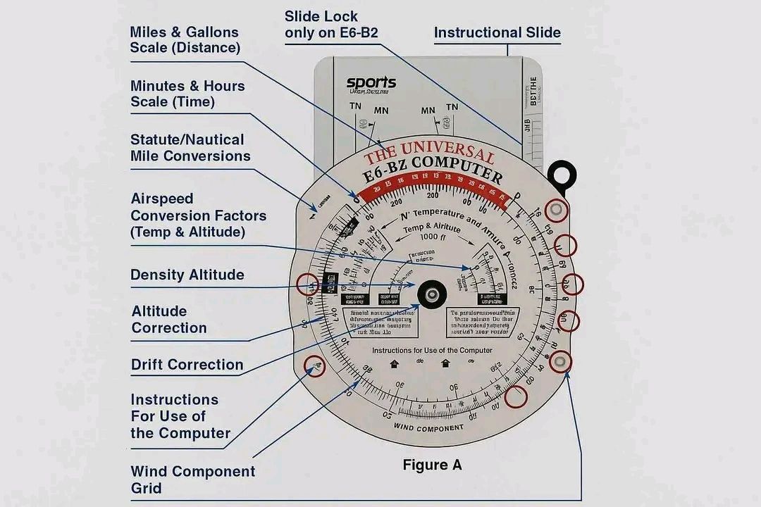
Lesson 5 — E6B Flight Computer Calculations
The E6B flight computer is a circular slide rule that solves the most common pilot math problems without electricity. You are required to know how to use it for your written test and practical test. Modern EFBs and apps do these calculations automatically — but understanding the underlying math makes you a better pilot and is tested on every written exam.
Time-Speed-Distance (TSD)
The fundamental relationship: Distance = Speed × Time. On the E6B, the rate index (marked "60" on the outer ring) is the pivot point for TSD problems. Set your known rate (groundspeed) on the outer ring against the rate index (60), then read time opposite any distance on the inner ring, or distance opposite any time.
TSD worked examples:
Find time: GS = 120 kts, Distance = 90 nm
Mental math: 90 ÷ 120 = 0.75 hr = 45 minutes
E6B: Set 120 on outer ring opposite rate index (60). Read time (45 min) opposite 90 on inner ring.
Find distance: GS = 105 kts, Time = 42 minutes
Mental math: 105 × (42/60) = 105 × 0.70 = 73.5 nm
E6B: Set 105 opposite rate index. Read distance (73.5) opposite 42 minutes on inner ring.
Find groundspeed: Distance = 65 nm, Time = 35 minutes
Mental math: 65 ÷ (35/60) = 65 ÷ 0.583 = 111.4 kts
E6B: Set 65 on inner ring opposite 35 minutes. Read outer ring at the rate index — that's your groundspeed (111).
Fuel calculations
Fuel calculations use the same TSD scale — just substitute fuel flow rate (gallons per hour) for speed and gallons for distance. The relationship: Fuel Used = Flow Rate × Time.
Fuel worked examples:
Find fuel used: Fuel flow = 8.5 GPH, Flight time = 2 hours 15 minutes (135 min)
Mental math: 8.5 × 2.25 = 19.1 gallons
E6B: Set 8.5 opposite rate index. Read gallons (19.1) opposite 135 minutes.
Find flight time on available fuel: Usable fuel = 38 gallons, Flow = 9 GPH, Required reserve = 30 min (4.5 gal)
Fuel available for flight = 38 − 4.5 = 33.5 gallons
Time = 33.5 ÷ 9 = 3.72 hrs = 3 hours 43 minutes of flight time before reaching reserve.
True airspeed (TAS) from indicated airspeed (IAS)
TAS increases approximately 2% per 1,000 ft above sea level because the air is less dense and the aircraft moves through it faster for the same IAS. The E6B wind side calculates exact TAS from pressure altitude and temperature: align the pressure altitude with the temperature in the airspeed window, then read TAS opposite IAS on the circular scales.
Quick mental approximation: at 8,000 ft pressure altitude, TAS ≈ IAS × 1.16 (16% higher than indicated). At 10,000 ft, TAS ≈ IAS × 1.20.
Wind correction angle (WCA) and groundspeed
Wind pushes the aircraft sideways and either adds to or subtracts from your groundspeed depending on direction. The wind side of the E6B (the circular grid) solves for the wind correction angle (how much to offset your heading into the wind to maintain course) and the resulting groundspeed.
The method: plot the wind direction and speed on the wind side, rotate the grid to your true course, and slide the grid to align with TAS. The wind correction angle reads directly off the grid, and the groundspeed appears at the grommet. This is a mechanical process — practice it several times before your written test until it's automatic.
The five calculations every pilot must do from memory
The E6B solves many problems, but five specific calculation types appear repeatedly — on the written test, on the oral exam, and in real cross-country planning. Master these five and you're E6B-ready.

Calculation 1: Time-Speed-Distance
This is the most common E6B calculation. Three variables, solve for any one: Distance = Speed × Time; Time = Distance ÷ Speed; Speed = Distance ÷ Time.
On the E6B: Set the speed on the outer ring over the "60" index mark. Then read time (in minutes on the outer ring) and distance (on the inner ring) opposite each other. Example: If groundspeed is 105 knots, how long to fly 65 nm? Set 105 over the 60 index. Find 65 on the inner ring. Read the time on the outer ring — approximately 37 minutes. Without the E6B: 65 ÷ 105 × 60 = 37.1 min.
Calculation 2: Fuel burn
Same wheel, different numbers. Fuel consumption (gal/hr) in place of speed; fuel burned in place of distance. Example: Engine burns 8.5 GPH. Flight is 2 hours 15 minutes. How much fuel needed (with 30-minute VFR day reserve)? Total time = 2:15 + 0:30 = 2:45 = 165 minutes. On E6B: set 8.5 over 60. Find 165 on outer ring. Inner ring reads approximately 23.4 gallons.
Calculation 3: Density altitude
On the E6B circular slide rule (back side of some models) or the density altitude calculation window: set the pressure altitude (field elevation adjusted for altimeter setting — if altimeter says 29.82 and field elevation is 4,000 ft, pressure altitude = 4,000 + (29.92 − 29.82) × 1,000 = 4,100 ft). Then align the temperature arrow to the OAT. Read density altitude from the window. Example: pressure altitude 4,100 ft, OAT 32°C (hot summer day in Utah): density altitude ≈ 7,200 ft.
Calculation 4: True Airspeed
TAS from IAS: Set the pressure altitude on the density altitude scale. Align the temperature. Read the correction — typically a percentage increase. At 8,000 ft and 5°C, TAS is approximately 14% higher than IAS. If IAS is 100 knots, TAS ≈ 114 knots. Most E6B calculators have a dedicated TAS window that shows this directly.
Calculation 5: Wind correction angle and groundspeed
This uses the wind side (slide) of the E6B. Plot wind direction and speed as a vector from the center grommet. Set true course under the true index. Slide the grid so the wind vector tip aligns with the TAS arc. Read wind correction angle from the center line deviation, and groundspeed from where the grommet aligns on the speed scale. This sounds complex but takes 2 minutes with practice. Practice it before every cross-country until it's automatic.
Lesson 6 — GPS in VFR Operations
GPS has transformed general aviation navigation. The Global Positioning System provides continuous, accurate position information to any aircraft with a GPS receiver. For VFR pilots, GPS is simultaneously the most useful navigation tool available and — if over-relied upon — one of the most dangerous.
How GPS works
GPS receivers calculate position by measuring the time it takes signals from multiple satellites (at minimum 4 for a 3D position fix) to arrive. Each satellite broadcasts its position and a precise timestamp. The receiver calculates the distance to each satellite and triangulates position to within a few meters under normal conditions. The US GPS constellation consists of 31 operational satellites in medium Earth orbit, providing global coverage.
GPS for VFR — the critical limitation
For VFR flight, GPS is classified as supplemental navigation — it is not FAA-approved as a sole means of navigation. The practical implication: always have a backup navigation method. A VFR cross-country should be planned with pilotage checkpoints and dead reckoning regardless of whether you have GPS. GPS databases can be outdated (airport data, airspace boundaries, and obstacles change), GPS signals can be jammed or spoofed, and receivers can fail.
The GPS dependency trap: Students who learn to navigate by GPS alone often struggle on their checkride oral when asked "where are you on the sectional?" and "what are your checkpoints?" Know how to navigate without the magenta line. Your DPE will ask — and if you can't answer, it signals a fundamental navigation gap.
RAIM — Receiver Autonomous Integrity Monitoring
RAIM is the GPS receiver's built-in self-monitoring function. It uses the geometry of available satellite signals to assess whether the position solution has sufficient accuracy and integrity for navigation. When RAIM is unavailable (too few satellites in useful geometry, or a satellite has been excluded due to a fault), the receiver alerts the pilot that the GPS position cannot be trusted for navigation.
For VFR flight, RAIM is less critical than for IFR — the visual references outside provide position confirmation. For IFR GPS approaches, RAIM availability at the time of approach must be confirmed during preflight planning. If RAIM is predicted to be unavailable during the approach, an alternate approach method must be planned.
GPS database currency
IFR-certified GPS units require regular database updates (typically every 28 days following the AIRAC cycle) to remain approved for instrument approaches. VFR GPS units have no legal database currency requirement, but using outdated data is unsafe — airports close, airspace boundaries change, and new obstacles are erected. Treat your GPS as you would a sectional chart: verify currency before relying on it.
What GPS does and does not do for you
GPS provides continuous, accurate position information. It shows you where you are, where you're going, how fast you're moving over the ground, and how long until you arrive. It does not show you weather ahead, traffic around you (unless equipped with traffic overlay), or airspace you're about to enter unless you have updated charts loaded. A GPS without current charts and without a weather overlay is showing you a blue line on a blank map — useful, but dangerous to trust completely.

Database currency — the currency requirement most pilots ignore
GPS aviation databases expire every 28 days (the AIRAC cycle). An expired GPS database can show outdated airspace boundaries, inaccurate approach procedures, and missing or wrong airport data. For VFR navigation, using an expired database is legal as long as you're aware of the potential inaccuracies — but it's bad practice. For IFR, instrument approaches must be flown with a current database.
More importantly: the chart overlay in your EFB (ForeFlight, Garmin Pilot, FltPlan Go, etc.) must be a current chart. Sectional charts are updated every 56 days. An outdated chart might show the wrong airspace boundary (a new TFR, changed Class D dimensions, a new runway), placing you in airspace you think you're clear of. Always verify your chart date before flight. Most EFBs show the chart expiration date prominently — check it before every cross-country flight.
The head-down trap — GPS's biggest danger
The most dangerous thing about GPS is not its failures — it's what it does to your visual scan. Every minute spent looking at the moving map is a minute not spent looking outside for traffic, terrain, and weather. Studies show that pilots with GPS spend significantly more time head-down than pilots navigating by chart. At 120 knots, you cover 2 nautical miles per minute. A 30-second head-down excursion is 1 mile of "eyes off" flight.
Discipline: use the GPS for strategic navigation (route, distance, ETA). Use your eyes for tactical awareness (traffic, weather, terrain, landmark confirmation). Set alerts for airspace before the flight so you're not hunting through menus while flying. Brief yourself on the route so the GPS is confirming what you already know rather than telling you things for the first time in the air.
GPS RAIM and signal integrity
RAIM (Receiver Autonomous Integrity Monitoring) is the GPS system's self-check — it monitors the quality of satellite signals and alerts you when position accuracy is degraded. Modern GPS receivers perform this automatically. A RAIM alert means the GPS position may not be reliable. For VFR navigation, continue with other methods (pilotage, VOR). For IFR approaches, a RAIM alert means you cannot fly the GPS approach — period. RAIM outages can be predicted; the FAA provides RAIM prediction tools for pre-flight planning, especially important for IFR flight in areas with limited satellite visibility.
Lesson 7 — Planning a Complete VFR Cross-Country
A complete cross-country flight plan integrates everything in this module: chart reading, TVMDC conversion, pilotage checkpoints, dead reckoning calculations, E6B math, and weather awareness. Here is the complete sequence, step by step.
Step 1 — Select your route
Draw a direct line from departure to destination on your sectional. Check for obstacles along the route — is the direct course over mountains or terrain requiring a specific altitude? Does it penetrate restricted airspace or MOAs? Are there TFRs? If the direct route has issues, plan a dogleg around them. Note 4–6 prominent landmarks along the route for pilotage checkpoints, spaced 15–25 nm apart.
Step 2 — Measure true course and distance
Using your plotter, align to the nearest meridian and read the true course for each leg. Measure distance directly on the chart using the latitude scale (1° = 60 nm, 1' = 1 nm) or your plotter's distance scale.
Step 3 — Convert to compass heading (TVMDC)
Apply the magnetic variation from the nearest isogonic line to convert TC to MC. Read the deviation from the compass correction card for the MC heading to get compass heading. Record all three (TC, MC, CH) on your nav log.
Step 4 — Obtain winds aloft forecast and calculate WCA/GS
Get the winds aloft forecast for your route from 1800wxbrief.com. Winds aloft are given in true direction and knots. Use the E6B wind side to calculate wind correction angle and groundspeed for each leg. Note: winds aloft are in true degrees — apply variation to convert to magnetic WCA before adding to MC to get magnetic heading.
Step 5 — Calculate fuel and ETAs
Using the calculated groundspeed, E6B TSD: time per leg = distance ÷ groundspeed. Sum all leg times for total flight time. Multiply by fuel burn rate (from POH performance charts at your planned altitude and power setting) for enroute fuel. Add required reserves (30 min day VFR, 45 min night VFR minimum — more if practical). Verify against usable fuel on board.
Complete nav log example — one leg:
Checkpoint: Springfield to Riverside (42 nm)
TC = 085° | Variation = 10°W | MC = 095° | Deviation = +3° | CH = 098°
TAS = 105 kts | Wind = 320° at 20 kts | WCA = −8° | MH = 087° | GS = 112 kts
Time = 42 ÷ 112 = 0.375 hr = 22.5 min | Fuel burn = 8 GPH × 0.375 = 3.0 gal
ETE from departure: 22 min | ETA (if departed 14:00Z): 14:22Z
Step 6 — Weather briefing
Get a full standard briefing from 1800wxbrief.com — not just an app check. Review: current conditions along the route (METARs), forecast at departure, destination, and alternates (TAFs), winds aloft, AIRMETs and SIGMETs, NOTAMs for all airports and the route, and TFRs.
Step 7 — File and open the flight plan
File a VFR flight plan — not legally required but strongly recommended. After takeoff, open the flight plan with FSS. After landing, close it immediately — or a search will begin 30 minutes after your estimated arrival time. An open, unclosed flight plan is a serious matter that activates search and rescue resources unnecessarily.
- TVMDC: True → (Variation: E subtract, W add) → Magnetic → (Deviation: from correction card) → Compass Heading
- Sectional charts: blue = towered airports, magenta = non-towered. Data block shows elevation, tower freq, runway length, UNICOM.
- MEF (large blue numbers) = highest obstacle in quadrant + safety buffer. Fly at or above MEF for terrain clearance.
- One degree of latitude = 60 nm. One minute = 1 nm. Use the latitude scale for chart distance measurement.
- Pilotage: identify two features simultaneously at each checkpoint. Never rationalize a feature match — if in doubt, fly to a known landmark and reorient.
- Dead reckoning: Distance = GS × Time. Compare actual vs estimated checkpoint times to identify wind differences from forecast.
- VOR: tune → identify (Morse code) → set OBS → track CDI toward needle. TO flag when heading toward station. Never navigate on an unidentified VOR.
- E6B TSD: set rate opposite rate index (60), read time or distance on inner ring. Fuel uses same scale with GPH as rate.
- GPS is supplemental for VFR — always have a pilotage/DR backup. RAIM confirms GPS integrity.
- Cross-country planning sequence: route → MEF check → TC measure → TVMDC → winds aloft → WCA/GS → fuel → ETAs → weather → NOTAMs → file plan.